Engineering Station
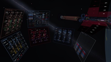
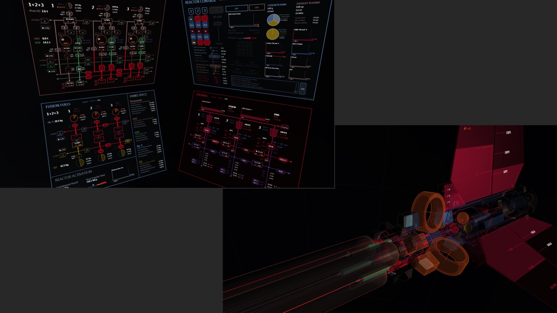
You will control the power plant and its support systems from there. It may seem a bit daunting at first but the ship’s automation and safety protections are here to assist your flight engineer.
Also each system is interfaced through a dedicated panel that clearly displays the underlying circuit. Moreover looking at the 3D animated schematic view will provide an overview of the ship’s state with one glance: items requiring immediate attention are flashing and can be immediately spotted.
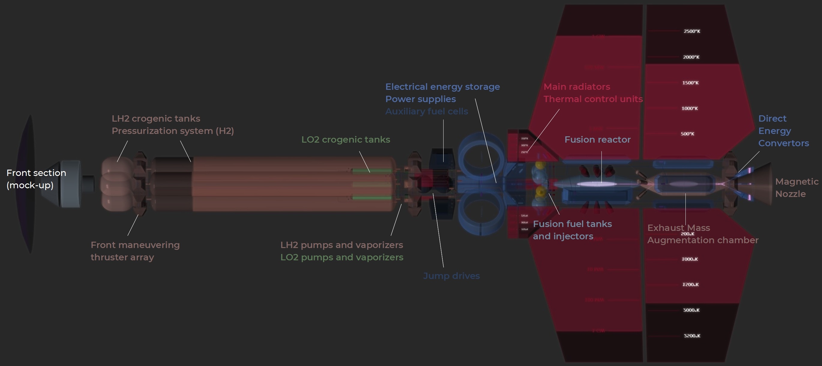
The main systems are indicated on the 3D schematic below. All are described in dedicated pages.
Redundancy scheme
With meteroids, cosmic rays, stellar winds and irradiance, radiation belts… spaceships evolve in a very harsh environment even without considering military operations. Also they run at very high powers that can put considerable strain on their systems. To make matters worse some flight paths can go through very remote locations where the chances of rescue in case of emergency are slim at best.
As a result all ships are designed with redundancy in mind and the CSN F9’s equipment is segmented into 3 sections on a 120° axial symmetry. A single segment is sufficient to perform all the ship’s functions, albeit at reduced capacity. Also it is not necessary that all active components should belong to the same section.
In all panels the normal flow is vertical, typically from a supply down to the consumers in the section.
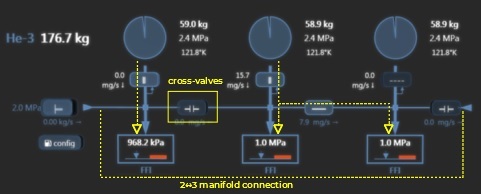
However manifolds are placed at critical points at which the circuits from different segments can be connected using cross-valves, normally left closed.
In the example to the left the He-3 tank of section 2 is supplying the fuel injectors (FFIs) of segments 2 & 3.
Note that all civilian ships and many military ones are built from only 2 sections. Also in order to save mass, strategies based on a main group and a backup one of reduced capability are also common (typically for short range vessels). That said in most configurations the sections are additive and the ship’s maximum performance can only be achieved with all sections active.
Main controllers
The block diagram below provides an overview of the CSN F9’s control schematic. The on-board controllers interpret the crew commands and manage the relevant actuators, factoring in the current systems’ state and equipment protection rules. In return they relay back information detailing the ship’s condition.
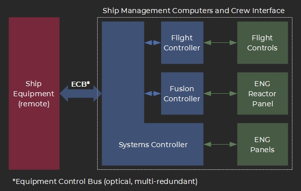
The Systems Controller communicates with the remote parts through the Equipment Control Bus.
All sub-systems acknowledge the received commands and transmit their state data, including self-diagnostic information for the most complex parts.
To complete the loop the received messages are treated and presented to the crew.
Reliability and maintenance
In order to help you keep your ship in good operational shape and minimize the risks of failure the systems controller is constantly monitoring the estimated wear rates on all parts.
The maintenance panel in the engineering station displays the extracted Estimated Time To Failure for all major components. This is the expected remaining time before a failure is likely to occur (in effect the part may continue to function but with a performance loss).
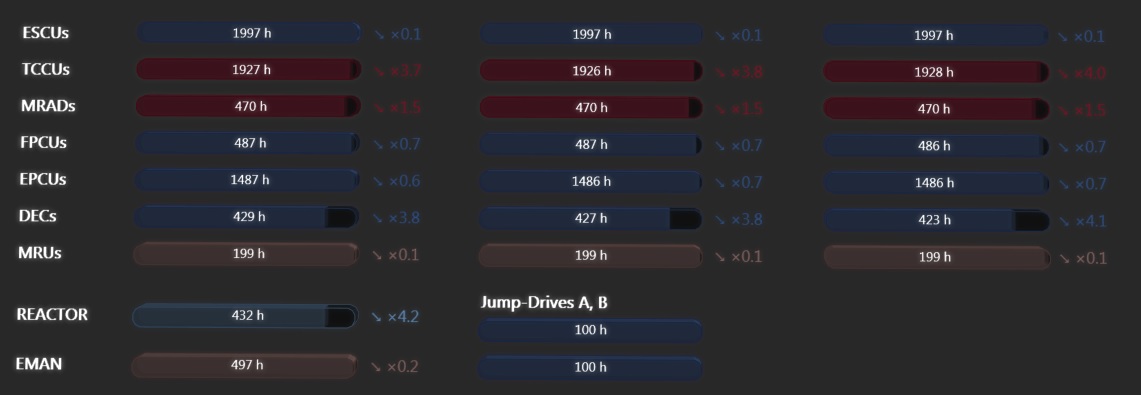
Besides all gauges are the estimated Wear Rate Acceleration Factors (x1 = nominal). Destructive rates are detected and trigger alarms.
At regular times you will have to schedule maintenance events at suitable orbital facilities. You will be able to select standard repair / replacement operations or pick new parts to upgrade your ship as you see fit.
Managing the ship’s systems is an important part of ASG’s gameplay. To make them as consistent as possible they are not hard-coded into the game as a complex set of pre-thought rules.
Instead they are described component by component and given a specific low-level model each. Then a custom electrical, thermal and fluidic circuit simulator animates the assembly of all sub-systems.
The fluidic and thermal domains are based on analogies with the electrical core. Across all domains the simulator ensures that:
[Conductances] * [Potentials] = [Flows]
where [Potentials] is the vector of the potentials at all the circuit’s nets, [Flows] is the vector of all flows entering all nets, and [Conductances] is the square matrix describing the conductances connecting related pairs of nets. The quantities in the three domains are:
- Electrical: conservation of the electric charge
potential = electric potential [V],
flow = electric current [A],
conductance = electric conductance [S = 1/Ω] - Thermal: conservation of energy
potential = temperature [K],
flow = heat flow [W],
conductance = thermal conductance [W/K] - Fluidic: conservation of mass
potential = pressure [Pa],
flow = mass flow [kg/s],
conductance = fluidic conductance [kg/s/Pa]
That is differences of electric potentials naturally generate electric currents, heat goes from hot sources to cold ones, fluids flow from high pressure points to low pressure ones.
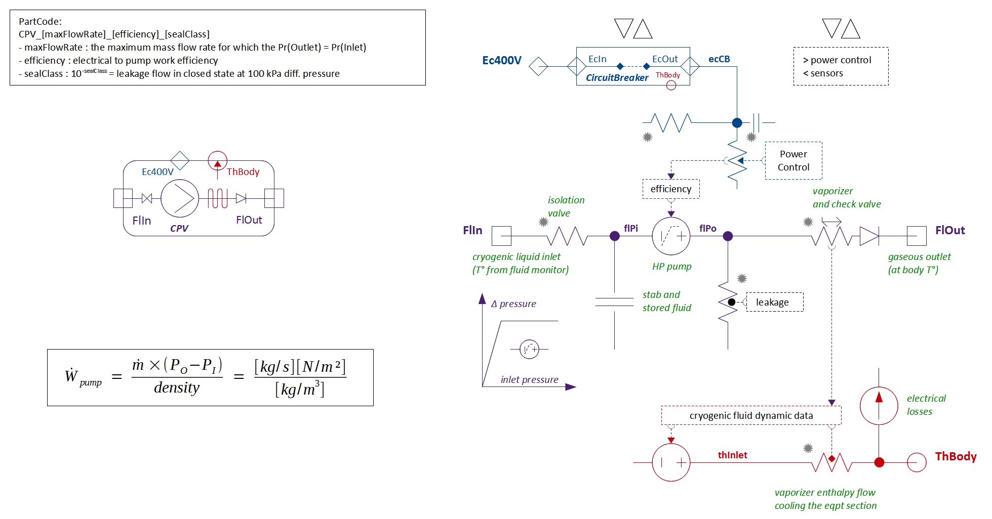
All parts are described as sub-circuits of elementary components. For instance below is the schematic for the LH2 and LO2 pumps and vaporizers. You can notice the interactions between the different domains: the mechanical work from the pump is taken from the electrical circuit, losses generate heat etc…