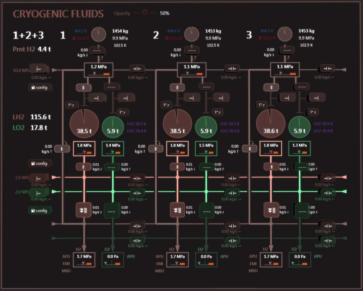
H2 circuit
LH2 tanks
Hydrogen is stored in 3 tanks following the ship’s redundancy scheme with a total combined mass of 119 tons.
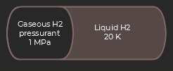 In each tank a sliding piston separates the pressurant gas from the LH2 contents. The regulated 1 MPa applied pressure and 20 K temperature (-253°C) keep the contents in pure liquid state, with a storage density around 70 kg/m³.
The tanks’ inner lining and walls provide a low permeation, excellent thermal insulation and high structural resistance. In case of abnormal thermal leakage a heat exchanger can help cool the contents using the ship’s cryogenic circuit. Nevertheless, should the LH2 temperature significantly increase the tanks are protected by 5 MPa pressure relief valves.
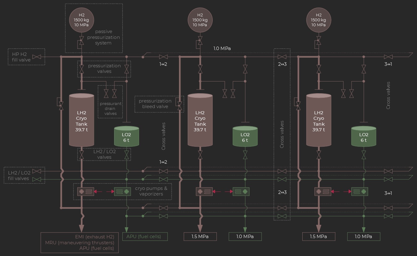
Cryo pump and vaporizer
After exiting the main tank the liquid hydrogen then goes into a vaporizer and boils into a gaseous H2 flow. The corresponding absorbed heat is provided by the ship’s support structure and the process thus participates in cooling the main reactor equipment. However the dense network of heat exchangers in the vaporizer opposes a significant fluidic resistance to the flow. Accordingly a 500 kW pump increases the LH2 pressure at the vaporizer input so as to maintain a target 1.5 MPa pressure at the H2 manifold.
Pressurization System
Two systems can provide the tank’s nominal pressurization (1 MPa):
- Normal configuration: a pressure regulated bleed valve connects the H2 manifold (vaporizer exit) back to the pressurant manifold.
- Backup: pressurization is provided by a high-pressure H2 tank (10 Mpa) and pressure regulated valve.
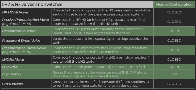
Valves and Switches
The table below summarizes the main controls in the H2 circuit and how they should be set in normal configuration.
LH2 balance and transfer
The contents in the three main tanks greatly influence the position of the ship’s center of mass (CoM). More specifically in case of imbalance the CoM moves away from the main axis which is also the thrust axis for the main engine. This is not an issue as the flight controller automatically adjusts the main thrust vector so as to cancel any average rotation torque.
However in certain circumstances it may be useful to transfer some contents from one tank to another in-flight, typically in case if a leak is detected:
- Depressurize the destination tank:
Pressurization Valve: CLOSED
Pressurant Drain Valve: OPEN - Make sure the source tank is pressurized
- Connect both tanks’ LH2 outlets via the corresponding LH2 cross-valve. You may want to isolate the other components from the manifold (unrelated LH2 valves and cryo-pumps CLOSED/OFF).
- Wait for the desired amount of LH2 to be transferred, close the LH2 cross-valve, return to a normal configuration for the remaining active circuit.