Heat Generation and Dissipation

In the ship everything generates heat:

  • The reactor obviously since it’s its main purpose. The problem is that some of the fusion power escapes the plasma and flows to the reactor vessel (fusion thermal load).
  • All active devices exhibit non-ideal efficiencies: part of their input power (generally electrical) is lost as heat and is transferred to the ship’s structure.

The space vacuum completely insulates the ship and consequently this accumulating heat cannot be conducted away (transferred to some surrounding matter). If nothing is done the result is an increasing temperature: dT/dt = Q/C, where dT/dt is the time rate of the temperature variation [K/s], Q the heat flow [W], and C the thermal capacity of the structure [J/K].

There are only two ways to vent the excess heat:

  • as internal energy of an exhaust fluid:
    Incidentally most of the heat waste comes from an incomplete thermal to kinetic conversion in the main engine nozzle and is simply carried away by the exhaust plasma. The water vapor produced by the APUs is another example. 
  • as an electromagnetic radiation:
    All objects radiate power depending on their temperature and surface characteristics (see Stefan-Boltzmann law below). The ship’s radiators are optimized for this function and total a combined emitting area of close to 5000 m².

The Stefan-Boltzmann law describes the thermal power (heat) emitted by a radiator as a function of its temperature:

Another cooling method consists in dumping the excess heat into a large on-board mass used as heat-sink. This mass must have a low initial temperature (lower than the structure to cool), and as heat flows from high temperatures to lower ones the warming heat-sink equally cools the hotter heat source. Incidentally the CSN F9’s cooling system uses the LH2 propellant as heat-sink.

The CSN F9’s Thermal Control System

The CSN F9 thermal control system makes use of both active and passive techniques to maintain all the power plant equipment within its specified temperature range under all power regimes.

CSN F9 space frigate: Thermal Control System

The whole temperature range is split into three main domains according to the specifications of the related equipment.

High Temperature Circuit

Temperature range: < 2000 K
Parts
:
Reactor vessel and EMA chamber
Cooling: Main radiators

Part of the radiation power emitted by the fusion and exhaust plasma gets past the reactor and EMA chamber’s internal high-reflectivity lining. At maximum fusion power the resulting thermal load can exceed 2 GW. To manage such a large heat flow the reactor’s support structure is made of a carbon-carbon lattice constituting a dense network of high temperature heat pipes and connecting it to the main radiators. The resulting very high thermal conductivity circuit ensures that the excess heat can be vented with minimum temperature difference between the radiators and the reactor, preventing the latter from overheating.

The three radiator wings total a combined geometric surface of 4854 m². Similarly to the reactor support structure they integrate a dense network of heat-pipes that maximizes their efficiency across their whole area (average emissivity 0.92). Their carbon-carbon building material ensures that they can withstand very high temperatures, which makes them very effective for a relatively low mass. Typical radiated power figures:

  • 1000 K → 250 MW
  • 1500 K → 1.3 GW
  • 2000 K → 4.1 GW

300 K domain

Temperature range: 200 K ↔ 400 K (-73°C ↔ 127°C)
Parts: main active devices
(TCCUs, FFIs, FPCUs, FIs, EPCUs, EMIs …)
Cooling: TCCUs (Thermal Control and Cryogenic Units) and LH2 / LO2 vaporizers

Most of the active equipment is designed to operate at “room temperature” (300 K ≈ 27°C). All the related components are connected to a support framework that is thermally insulated from the high temperature parts. Integrated heat pipes route the excess heat towards the thermal control units (TCCUs) and LH2/LO2 vaporizers.

The 300 K circuit follows the general redundancy scheme and the three sections are insulated from one another by default. However they can be connected through controllable heat exchangers (thermal conductivity 100 kW/K).

TCCU cooling

High-power, high-performance refrigeration units provide the main cooling method for most of the ship’s equipment. Heat is extracted from the support structure and transferred to the main radiators. The electrical EQPT bus (20 kV) powers the compressors providing the required work.

Refrigeration systems are characterized by their Coefficient of Performance COP = Q / W where Q is the transferred heat (desired effect) and W the input work (cost).
The COP cannot exceed its theoretical thermodynamic limit = TL / (TH – TL)
where TL is the temperature of the structure being refrigerated and TH the temperature of the reservoir receiving the extracted heat. Here TH is the temperature of the main radiators, typically 1800 K at high fusion power and TL = 300 K. This yields a maximum value of 0.2, that is for every joule extracted from the equipment a bit more than 1 + 1 / 0.2  = 6 J are dumped into the radiators.
To compensate for this loss of efficiency the TCCUs’ power rating is around 200 MW (electrical input). This is necessary to maintain a heat transfer capability > 25 MW under all circumstances.
The temperature regulation is automatic (Pulse Width Modulation scheme). Similarly the TCCUs operate at discrete power levels and the adequate one is automatically and dynamically selected (with possible manual override).

Main thermal indicators in the 3D schematic view

LH2 heat sink

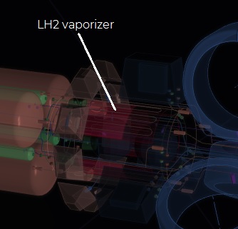
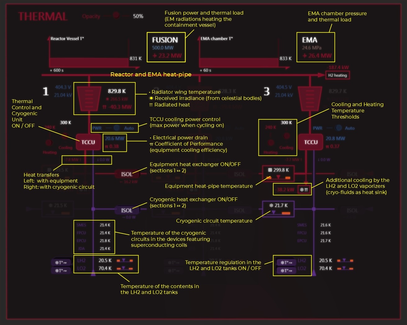
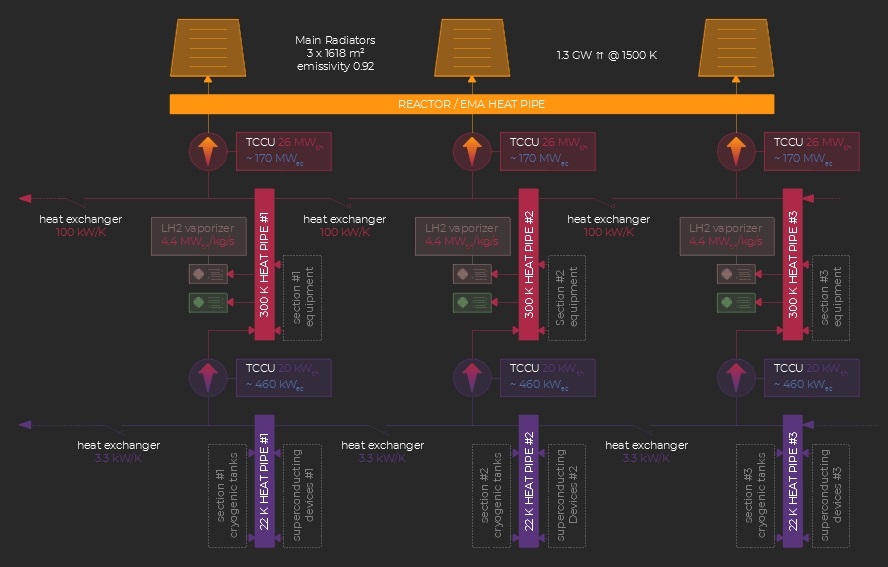
As mentionned above the CSN F9’s systems make use of the on-board hydrogen as an auxiliary heat-sink to help cool the main equipment.

Hydrogen is stored in its cryogenic liquid state at 20 K. When flowing through the LH2 vaporizers it first boils to its gaseous state and then is further heated to approach the equipment’s temperature (nominally 300 K).
The two processes require heat, which is actually extracted from the equipment’s support structure thanks to a dense network of heat exchangers.
The resulting cooling amounts to 4.4 MW/kg/s at 300 K.

This effect depends on the hydrogen flow and is thus much more important during burns. Nevertheless it is still very beneficial because this is also precisely when the reactor is operating at high power and when the TCCUs lose most of their efficiency.

Incidentally this is another reason why very lean thrust regimes should be avoided at high fusion power. Besides the possible damage to the DECs the relatively small hydrogen flow also significantly limits the auxiliary cooling and increases the load on the TCCUs.

Note: when flowing LO2 also contributes to the auxiliary cooling.

300 K Heating

With no heat source the equipment’s temperature may also decrease and approach its low operating limit, typically when coasting for long periods with the reactor shut down and in cold space regions. The TCCUs also integrate heaters to deal with such situations.

Cryogenic circuit: T = 22 K

Despite the advancements in low electric resistivity meta materials typically employed for high power lines, superconducting coils are still mandatory to generate the most powerful magnetic fields. In the CSN F9 the SMES units (energy storage), FPCUs & EPCUs (plasma confinement), and  the jump-drives all make use of superconductors. The critical field temperature for all these devices is 57.7 K (-215.5°C).

To support this equipment the TCCUs integrate 460 kW cryocoolers with a COP ≈ 0.04 to provide around 20 kW of heat transfer capability down to 22 K. Heat pipes then connect the TCCUs to the devices in need of cryogenic cooling.

Similarly to the 300 K domain, the cryogenic circuit follow the global redundancy scheme with three distinct heat-pipes and switchable cross heat exchangers (3.3 kW/K).

Notes:
– The cryogenic circuits of Jump Drive A and B are connected to sections #1 and #2 respectively.
– By default the cryogenic tanks (LH2 and LO2) are not connected to the cryogenic circuits but heat-exchangers can be activated on the thermal control panel (engineering section).

Space Environment

Most of the time the thermal radiation from the surrounding stars (irradiance) will not pose significant problems to a CSN F9 (though solar winds and ionizing radiations might). Its external armor exhibits a high reflectivity (typically 97 %), its components are efficiently thermally insulated, and it is fitted with a powerful heat management system as presented above.

That said the main radiators are by design as good receivers as they are emitters and so their equilibrium temperature will depend on the incoming irradiance. For instance supposing a power regime with 3 GW of radiated heat, an irradiance of 1 GW will change the radiators temperature from 1850 K to 1990 K. This may lead to overheating issues.
However the maximum equivalent surface exposed to a nearby source is 809 m² and so 1 GW corresponds to 1.2 MW/m². This would mean cruising only 5 million km from a G2V star which is very unlikely.

Furthermore the attitude controller features an “Irradiance” mode that will orient the ship so as to minimize its equivalent surface with respect to the incoming radiation.

The CSN F9's thermal control panel