Multiple Simultaneous Reactions

This section describes the fusion reactions at work in the CSN F9’s power plant (and in most spaceships).

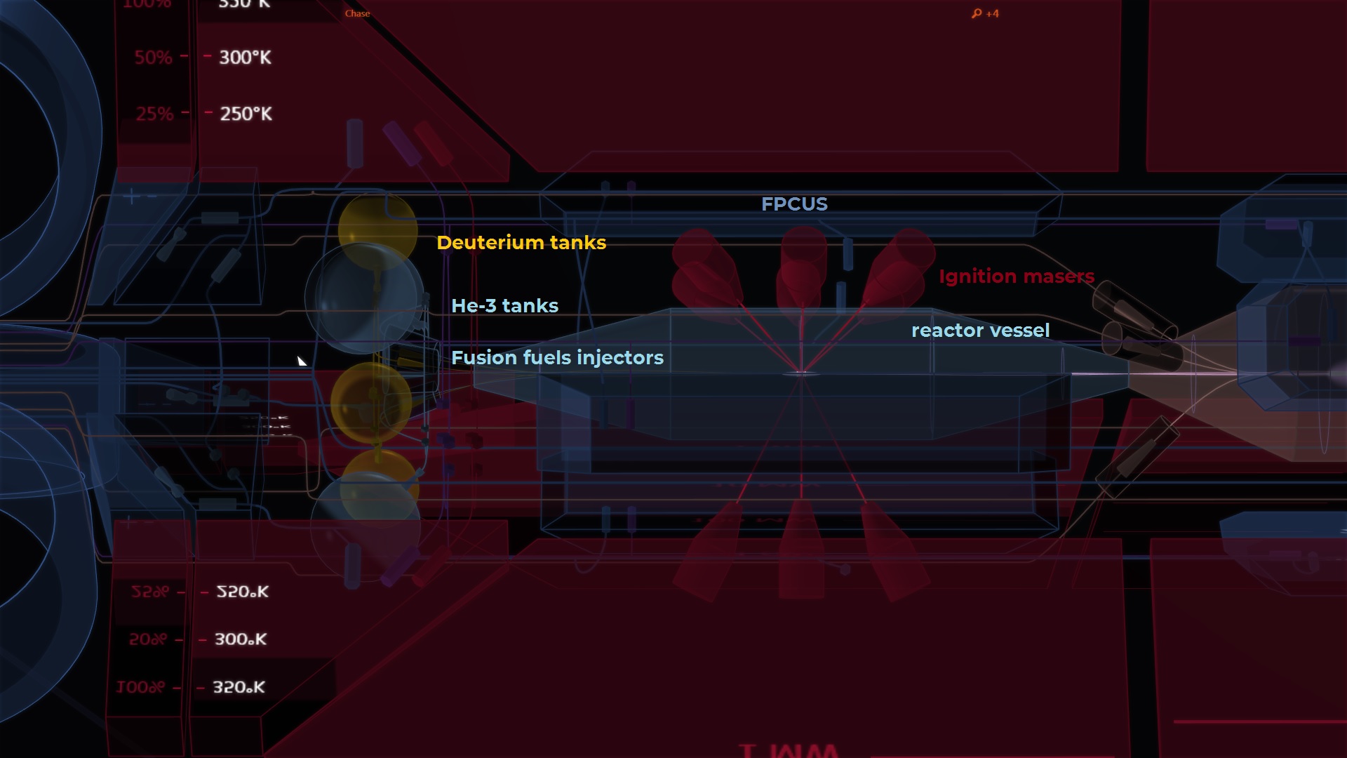
Nuclear fusion is an event during which the nuclei of two atoms combine into a heavier element. The total mass of the products is a little less than the sum of the reactants and the difference comes as an energy ΔE = Δm c². However this is very difficult to trigger because nuclei are positively charged (they contain protons) and the electrostatic force makes them repulse each other in 1 / d² where d is there relative distance. A possible way is to have Fusion Ignition masers (FI) heat the reactants to very high temperatures and thus impart their particles with very high kinetic energies. In the process they reach a state where atoms get fully ionized (nuclei are dissociated from their electronic cloud) that is called a plasma, and at sufficiently high temperatures there exists a non-zero probability for colliding nuclei to overcome the electrostatic force and fuse. This probability is expressed as the reaction’s cross section.

To add to the difficulty plasmas cannot be contained using normal materials: a small quantity of plasma coming in contact would instantaneously cool off, and a large one would melt  → vaporize → ionize the containment vessel. However because they are gases of individually charged particles plasmas can be confined using magnetic fields. Incidentally Fusion Plasma Confinement Units (FPCUs) are the components handling the fusion plasma in your ship.

  • D is a nucleus of deuterium (1 proton + 1 neutron)
  • T is a nucleus of tritium (1 proton + 2 neutrons)
  • He-3 is a nucleus of helium-3 (2 protons and 1 neutron)
  • He-4 is a nucleus of helium-4 (2 protons and 2 neutrons)
  • p is a proton (H+) and n is a neutron
  • eV (“electron-volt”) is a measure of energy used in nuclear physics, 1 eV = 1.6e-19 J, 1 MeV = 1.6e-13 J
  • eV is also used to express temperatures through the Boltzmann constant (1.6e-23 J/K): 1 eV / kB = 11605 K

The reactions of interest are principally:

  • D + T → He-4 (3.5 MeV) + n (14.1 MeV)
    This is the most favorable reaction due to its high cross-section (probability of fusion after a collision of the reactant nuclei) and lower temperature of peak activity (~ 100 keV). However a major part of the produced energy is carried out by a neutron that naturally escapes the magnetic confinement. In space engines it is necessary to drive as much of the present elements and energy towards the exhaust nozzle, and consequently the D + T reaction is not well suited for this usage.
  • D + He-3 → He-4 (3.6 MeV) + p (14.7 MeV)
    While it is close to 10 times less active and peaks at much higher temperatures ( ~400 keV), D + He-3 is aneutronic which explains why it is the one retained for space engines. However in effect this is not truly the case because deuterium nuclei can react between themselves :
  • D + D  → T (1.01 MeV) + p (3.02 MeV), 50 % probability
    D + D → He-3 (0.82 MeV) + n (2.45 MeV), 50 % probability
    Compared to D + He-3 the activity of the D+D reactions is 4 times smaller and they peak around 2000 keV. However they are not negligible and neutrons are still a concern with Deuterium / Helium-3 reactors especially at high power. To alleviate the problem the mix of reactant can be altered and more concentrated in He-3. However this leads to more plasma for a given power, which increases the electromagnetic losses (bremsstrahlung and synchrotron radiations) and the strain on the confinement units due to the higher plasma pressure.

Below is a plot of the respective cross sections (simplified model)

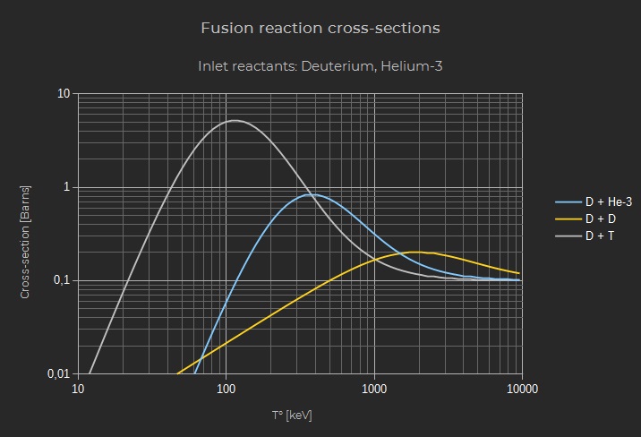
Note: 1 Barn = 1E-28 m²

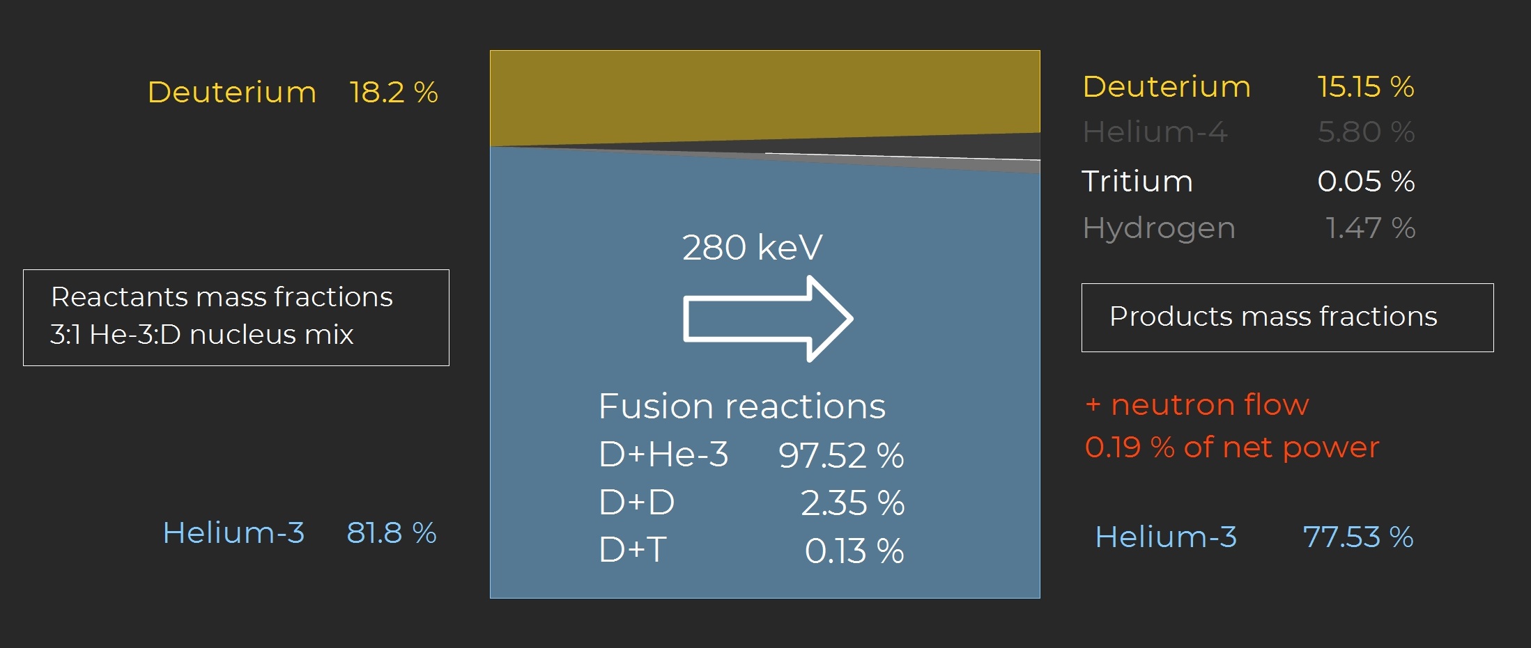
Deuterium + Helium-3 Steady State

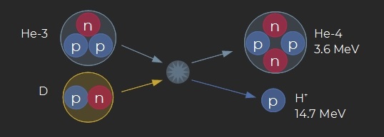
In steady state an inlet mix [D + He-3] at 3 He-3 nuclei per D nucleus yields the reactions and mass fractions as shown below. A very small portion of the reactants is actually consumed but this is a consequence of the necessary fusion control loops.

Fusion reaction steady state with Deuterium Helium-3 reactants, 1:3 nucleus mix

Note: helium-3 is very rare and is primarily extracted from gas and ice giants. Specifically designed carrier ships launch unmanned drones onto partial atmospheric braking trajectories. Friction ionizes the gases around the vehicle and He-3 is then selectively scooped using mass spectrometry techniques. While there is no shortage of Helium-3 throughout Alliance space its extraction remains very expensive and so is its price.

Main reactor components in the ship's engineering schematic view

Fusion control

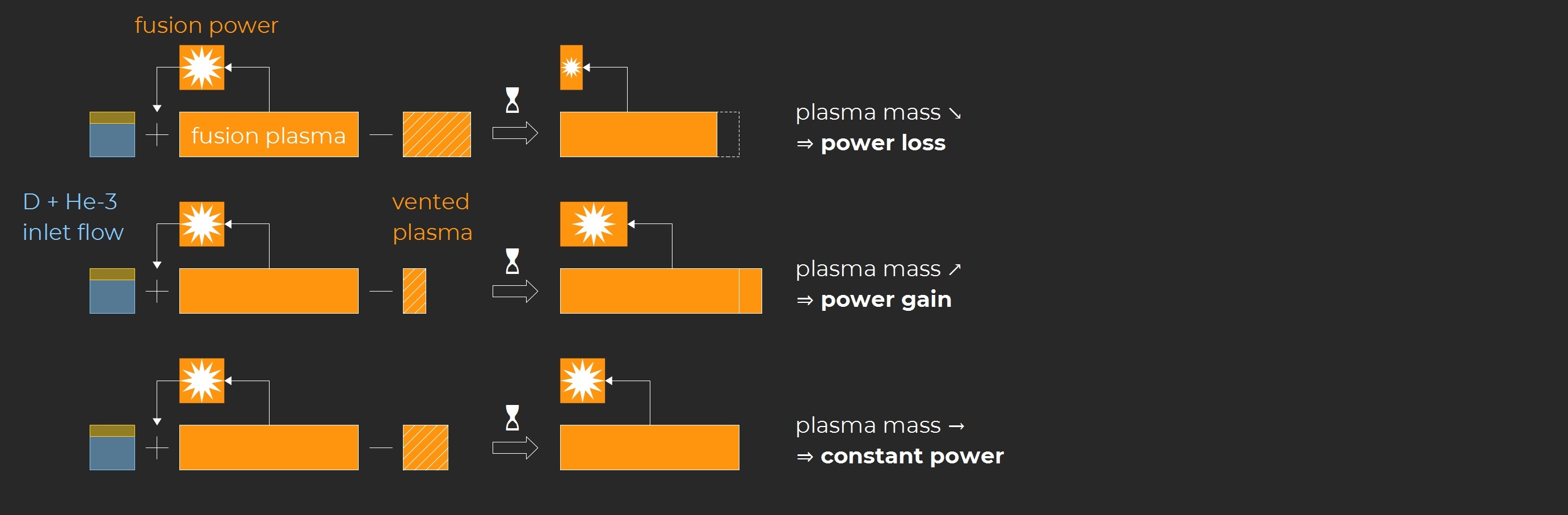
The event rate of the fusion reactions is given by cross-section <A,B> * density of reactant A * density of reactant B. Considering a constant confined volume in which the fusion takes place it derives that the fusion power evolves as the square of the plasma mass.
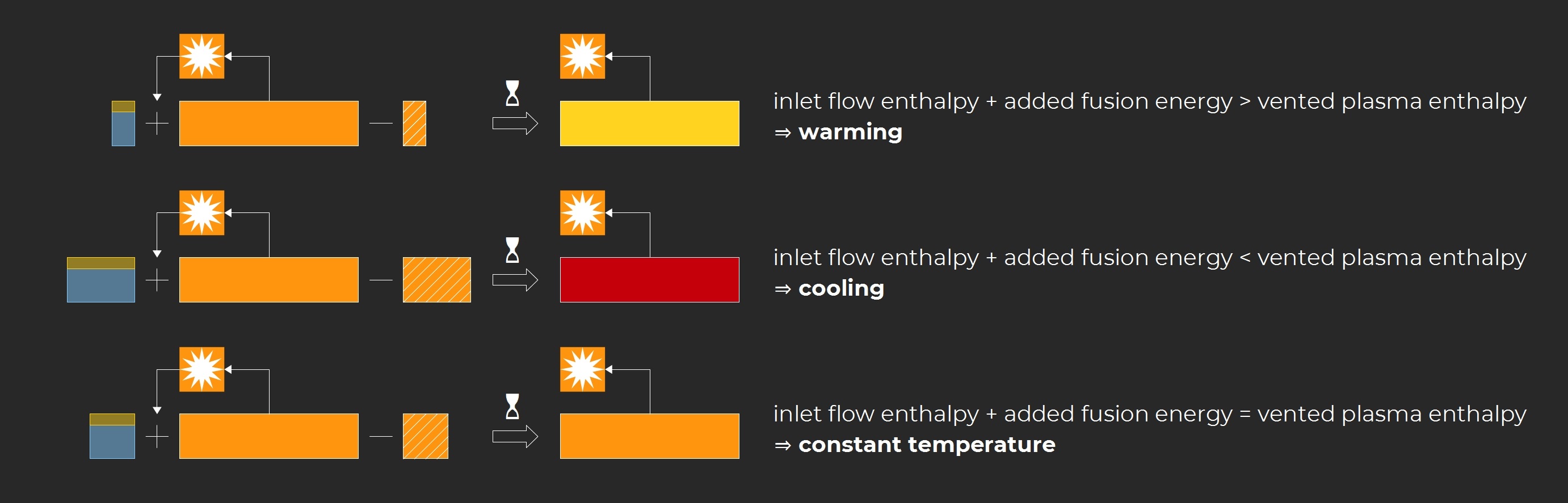
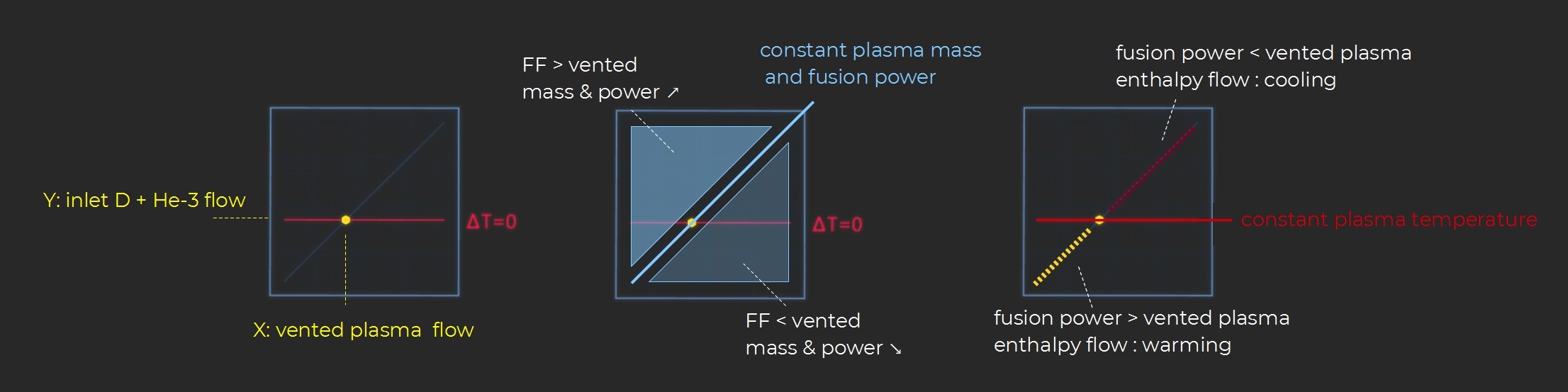
Additionally the plasma composition must remain constant as reactants are consumed, which requires a sustained inlet flow of deuterium and helium-3. As a result an equivalent stream of plasma must be vented to maintain a constant mass. In effect the fusion controller regulates the power through the modulation of the vented plasma flow.

Fusion power control
 
So in the steady state inlet fuel flow = vented plasma flow. The effective value can be determined considering that besides its mass the energy of the plasma must also remain constant. That is for a given time interval inlet flow enthalpy + generated fusion energy – vented plasma enthalpy = 0. The inlet flow carries very little energy since it is relatively very cold so the equation roughly simplifies as generated fusion energy = energy carried out by the vented plasma. Incidentally this is the way the fusion power is transmitted to the EMA chamber.
A constant plasma energy is equivalent to a constant plasma temperature (energy [J]= heat capacity [J/K] * temperature [K]) and can thus be regulated by the fusion controller through a modulation of the total circulating flow (inlet fuel and matched vented plasma flow).
Fusion temperature control
Note that the process can also be understood looking at the inlet and considering that the fusion power must equal the amount needed to heat the incoming cold flow to the desired plasma temperature (even if the inlet flow is gaseous and is therefore ionized, the related energy – change of state – is negligible with respect to the required tremendous elevation of temperature).
 
Interestingly at 50 GW the stored plasma energy is around 3900 GJ, that is a little short of 1 kiloton of TNT. This is the main reason why ships are not authorized to approach a station by less than 10 km with a running reactor. Furthermore full power thrust is allowed only with at least with 100 km separation. In the latter case both the stored plasma energy and the extent of the exhaust plasma plume are to be considered.
 
To sum-up the fusion controller is simultaneously adjusting the inlet and vented plasma flows to regulate both the fusion power and the plasma temperature. You can monitor its activity looking at the flow gauge on the reactor panel in the engineering station. The yellow dot represent the flows (logarithmic scales). The blue diagonal is the line of constant plasma mass (inlet = outlet). The red horizontal line marks the position of constant energy and temperature.
This is demonstrated in the following video:

Magnetic confinement

In the CSN F9’s reactor the Fusion Plasma Confinement Units drive the fusion plasma into a Field-reverse configuration. The FPCUs automatically adjust their activity to maintain the desired β = the ratio of the plasma pressure over the induced magnetic confinement pressure. The nominal β is 0.2.

The control from the FPCUs is dynamic as they are actively damping a plasma that exhibits many instability modes. Maintaining the required β becomes more difficult when approaching their nominal pressure rating. In such conditions the fusion regime becomes less steady.
The key factor setting the strain on the FPCUs is the plasma pressure which varies like its mass * temperature product. Typically running with He-3 rich / low neutron mixes requires more plasma at a given power and thus more confinement pressure. As a result temporary power surges for emergency maneuvers may be achieved with more balanced (and “neutron dirty”) mixes.

Fusion losses

The fusion plasma is primarily losing power through the brehmsstrahlung and cyclotron radiations. Both are produced by the acceleration of charged particles. In the first case these are deflecting one another due to the electrostatic force. Any lost kinetic energy is radiated away (conservation of energy) which is why the bremsstrahlung is also called “braking radiation”. Cyclotron losses are more specifically related to the magnetic containment: particles spiral along the lines of the magnetic fields because of the Lorentz force.

These losses are electromagnetic (photons) and are not submitted to the confinement fields. However the reactor vessel (physical) is lined with wide-band high-reflectivity refractory metallic meta-materials (overall reflectivity ~ 0.85). The radiation going through is the thermal load that is absorbed in the surrounding structure as heat. At 50 GW the heat flow typically reaches 2.2 GW that are dissipated by the main radiators.
Similarly to what happens with the FPCU strain, the thermal load increases with more plasma mass.

Neutron dose rate

The deuterium / helium-3 reaction is said to be globally “aneutronic” because the energy carried out by the neutron flow is less than 1 % of the fusion power (typically 0.19 % in the case of CSN F9 reactor at nominal settings). However this still amounts to about 100 MW at 50 GW. Without shielding the neutron fluence would reach 800 W/m² 100 m away (ship’s crew quarters), that is about 0.16 W/kg or 0.16 G/s ~ 0.16 S/s if it were totally absorbed by biological tissues (G stands for Gray, S for Sievert, both equivalent to J/kg). This is a deadly dose in a matter of seconds.
To overcome the problem the reactor vessel constitutes a high-efficiency boron-enriched neutron trap that captures all but a few escaping neutrons. About 3/4 of the flow is trapped by the working fluids of its embedded heat transfer lattice while the remaining 1/4 gets ingrained into the support structure itself. With time the reactor vessel itself is getting “activated” (damaged) by the captured neutrons, degrading its performance and accelerating its wear rate. The heat transfer fluids can be regularly changed to delay the effects but eventually the reactor vessel must be replaced. This is a very costly operation and as such conducting  as “clean” as possible operations is a very beneficial strategy.

A sincere thought for all engineers and scientists who face real physics every day to make controlled civilian fusion a reality!