Circuit diagram

The CSN F9’s electrical system features 3 main types of components:
>> Electrical Energy Storage devices (SMES,  batteries) <<
>> Power Generators (DECs, APUs) <<
>> Distribution Buses (BATT, EQPT, MAIN) <<

CSN F9 space frigate: Electrical System schematic

It follows the global redundancy scheme with 3 independent sections and a main bus also acting as a crossfeed line.

Buses and Switches

All power distribution lines are built from low-resistivity meta-materials and connected to the main 300 K equipment heat pipes for cooling. All buses provide both 400 V and a 20 kV DC supply dedicated respectively to regular and high-power devices.

BATT bus

Essentially the connection point for the ESCUs (Energy Storage and Conditioning Units) which manage all the main on-board electrical energy storage and feature the primary 20 kV and 400 V power supplies.

EQPT bus

Distributes the electrical power to the reactor and main engine equipment for one section:
– TCCU (thermal control)
– All tanks, valves and pumps
– FPCU and EPCU (plasma confinement)
– FFI and EMI (fusion fuel and exhaust H2 injectors)
– FI (fusion ignition plasma heaters)

Also connects the power generators for the section:
– DEC (exhaust plasma heat to electrical power magnetohydrodynamic converters)
– APU (H2+O2 back-up fuel cell)

MAIN bus

The main bus is redundant in itself and is meant to transfer the electrical power from the power plant to the rest of the ship. It connects:
– all 3 MRUs (maneuvering thrusters)
– JDA and JDB (jump-drives)
– the ship’s armament
– the ship’s front section (crew quarters and life-support systems, sensors, avionics)

Power switches

All buses are isolated and connected to the rest of the network through high-power switches controlled from the electrical panel in the engineering section (and operating simultaneously on the 400 V and 20 kV lines).
By default all switches are locked to avoid any unwanted operation whenever the reactor is running (the electrical network can then still be reconfigured by temporarily removing the safety fusion lock as required).

Fusion lock on sections 1 & 3, removed on section 2

Power Generators

DEC

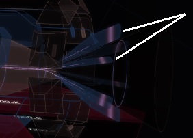
The Direct Energy Convertors are magnetohydrodynamic generators that convert the exhaust plasma’s thermal energy first into kinetic energy through an internal nozzle, then into electrical energy using a magnetic field to drive the accelerated charged particles towards collecting electrodes. They do not feature any moving part and their low mass has made them the technology of choice for electricity generation in spaceships. Indeed they are the CSN F9’s primary electric generators.

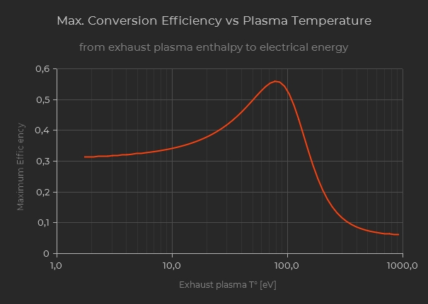
DECs are optimized for an input plasma temperature and their efficiency steadily drops outside of their specified range. Consequently when the EMA chamber is in DEC mode (no thrust) the fusion controller regulates the exhaust plasma temperature for optimum electricity generation.
However in THRUST mode care must be taken to keep the plasma temperature low enough (typically < 150 eV) or risk a significant increase in the device ‘s wear rate. Under such circumstances the controller must increase the plasma feed to compensate for the lower overall efficiency, and the incomplete energy conversion also leads to hotter particles ablating the collecting electrodes. A safe operation can be achieved by avoiding very lean regimes and limiting the fusion power with respect to the desired thrust.

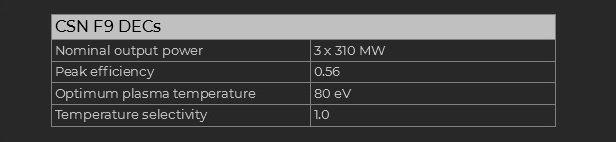
The following table and plot summarize the specifications for the CSN F9’s DECs:

APU

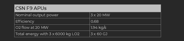
Three auxiliary H2 + O2 fuel cells provide back-up electrical power when the reactor is offline:
2 * H2 + O2 → 2 * H2O + [ 10.4 MW / O2 kg / s, η = 0.68 ]
Their main purpose is to (partially) recharge the main energy storage units and enable a fusion re-start in deep space. The hydrogen is taken from the main H2 lines and auxiliary LO2 tanks, cryo-pumps and vaporizers provide the oxygen reactant. The water vapor product is vented directly into space to avoid wasting energy in the cooling system.

Note: Oxygen is heavy and 18 tons significantly impact the ΔV budget. Moreover experienced flight engineers can start the reactor with much less than 180 GJ and thus many crews generally undock with a half LO2 complement (the life-support oxygen is stored in independent tanks in the front section).

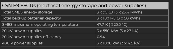
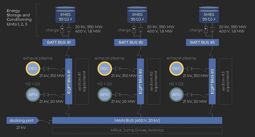
Energy Storage and Power Supplies

SMES

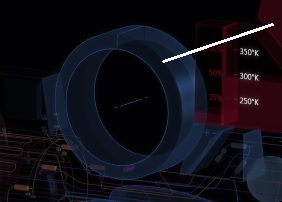
Three Superconducting Magnetic Energy Storage units constitute the CSN F9’s primary electrical energy reserve. SMES store electricity as a high-intensity direct current flowing through superconducting coils. Superconductivity ensures a zero parasitic resistance and consequently no discharge over time. Incidentally the SMES units are connected to their respective section’s cryogenic circuit and their maximum operating temperature is 47.7 K (-225.5 °C).

The SMES are connected to the BATT bus through the ESCUs (Energy Storage and Conditionning Units)

The purpose of the SMES units is manifold:

  • provide energy to the reactor equipment during the fusion start-up sequence (DECs offline)
  • power the maneuvering thrusters (MRUs) during the fusion start-up sequence (DECs offline)
  • complement the supply from the generators when the power consumption temporarily exceeds their output

Note: quenching protection. The SMES coils hold very large amounts of energy and it is thus vital to prevent them from “quenching” that is abnormally leaving their superconductive state. Under such circumstances the stored energy would be released in thermal form and yield an explosive destruction of the device, with possible catastrophic propagation to the surrounding equipment. 
Consequently all SMES are fitted with Emergency Discharge Units (EDUs) that are automatically activated to dissipate the stored energy (as heat into the main radiators) when approaching dangerous conditions (typically rising temperatures).

Batteries

Three conventional chemical batteries provide a last-resort backup to be able to operate the low-power equipment in case no other source is available. This typically includes being able to set up the H2 and O2 circuits to supply and start the APUs. Similar to the SMES the batteries are connected to the BATT bus via the ESCUs.

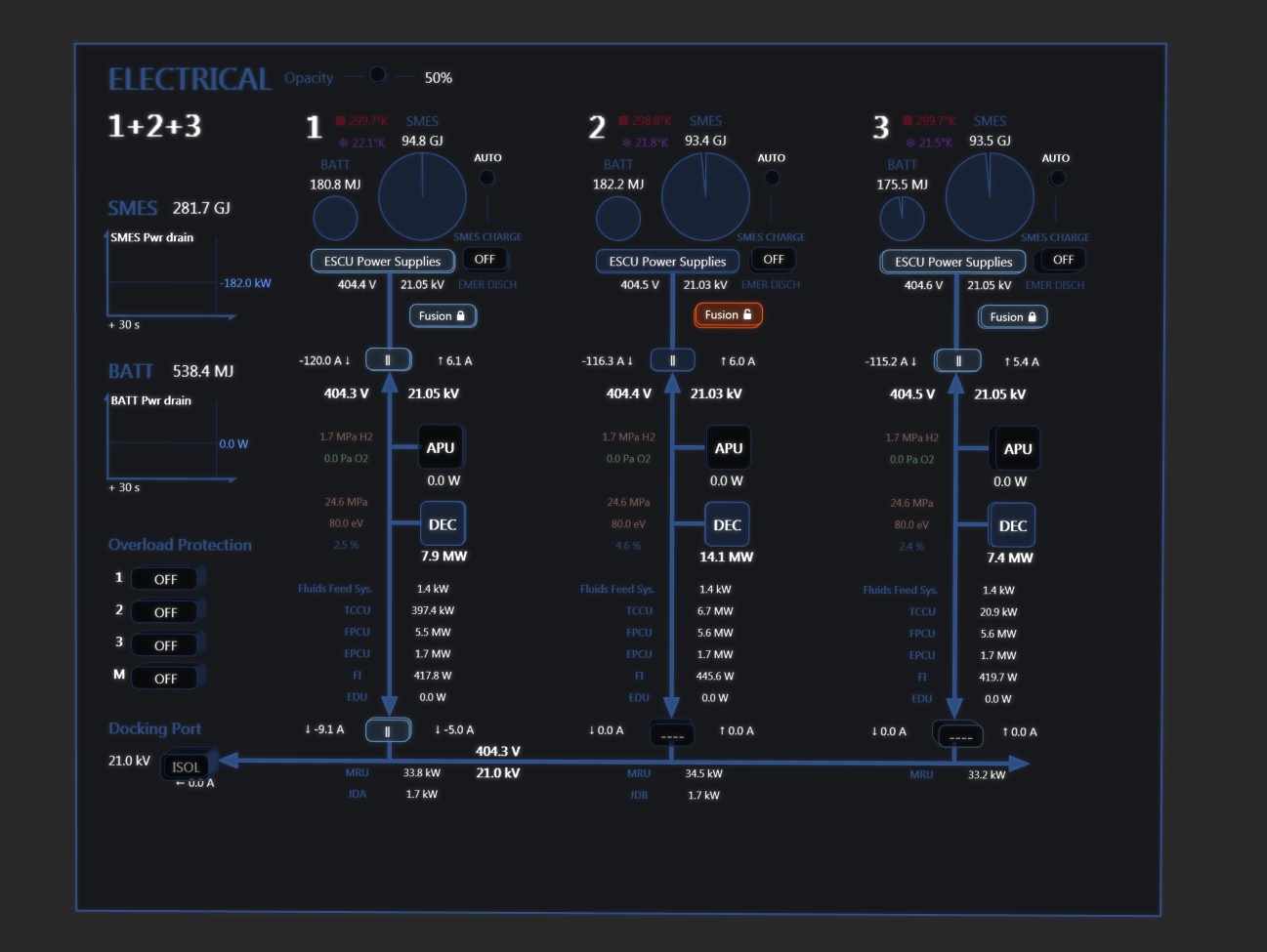
Power supplies, SMES (and battery) recharge

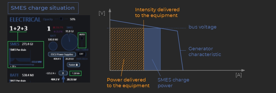
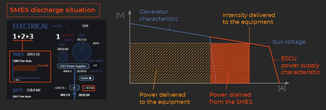
The Electrical Storage and Conditioning units (ESCUs) manage and connect the SMESs and batteries to the respective BATT buses. They can both source and sink electrical power to and from the bus according to the current power balance:

  • The SMES (and battery) are recharged whenever the generators’ supply capability exceeds the load from the connected equipment (and the [SMES charge] function is set to AUTO).

  • The ESCU power supplies provide the required complementary power whenever the load from the connected equipment exceeds the generators capability. The necessary energy is drawn from the SMES coils (then the batteries).

Note: 400 V bus lines. All generators (including space stations via the docking port) deliver their power at 20 kV only. The 400 V is generated by DC-DC converters in the ESCUs.

Normal configuration

  • The equipment for each active section should be connected to its ESCU:
    ESCU ON
    BATT to EQPT switch CLOSED (ON)
  • The SMES charge function should be active and the quenching protection armed:
    SMES CHARGE AUTO
    EMER DISCH ARMED
  • One single generator should be active on the EQPT bus:
    DEC ON (automatically engaged by the fusion controller)
    – APU ON (as required, DEC OFF)
  • One single section should power the main bus:
    EQPT to MAIN switch 1 xor 2 xor 3 CLOSED (ON)

Notes regarding the main bus:
– A good practice is to choose the connected section so as to balance the wear and tear on all three ESCUs (maintenance is less costly when treating as much equipment as possible while the ship is immobilized).
– Whenever a very high power is required on the main bus (that is exceeds one section’s generator + ESCU capability) it is possible to connect several sections in parallel (all the voltage sources are protected by high-power diodes). However using such a configuration in normal circumstances is not advised as there is then no control over how the load is spread between the different sources.