Attitude and Thrust controllers, Flight Guidance System
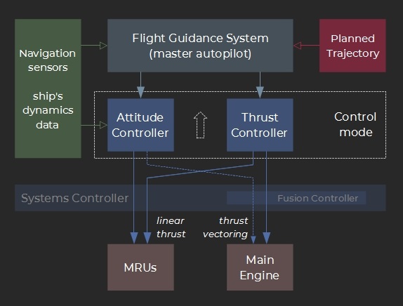
The block diagram below presents the CSN F9’s flight control system. The ship’s Inertial Navigation Units (INUs) collect and feed the necessary real-time inputs (attitude, location, velocity, mass, center of mass location, moments of inertia). The flight planner provides the reference trajectory data for the flight guidance system (master autopilot).
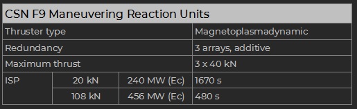
Maneuvering Reaction Units (MRU)
- Attitude control
- Course corrections
- Station keeping / relative flight
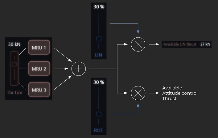
- The Maneuvering Systems panel (helm station) regroups the MRU related controls.
- The LIN and ROT sliders divide the total thrust between the linear (translation) and rotational (attitude) modes respectively,
with LIN + ROT ≤ 100% (e.g. 20% / 20% is a valid setting that limits the total allocated thrust).
The thrust and attitude controllers automatically adjust their dynamic response to the available thrust.
- The Power Saturation slider controls the allocated electrical power as a function of the commanded thrust.
The typical usage is to remain in the [linear] setting while the reactor is offline to limit the power drain. Then switching to [medium] when the main generators are running ensures a lower consumption of hydrogen.
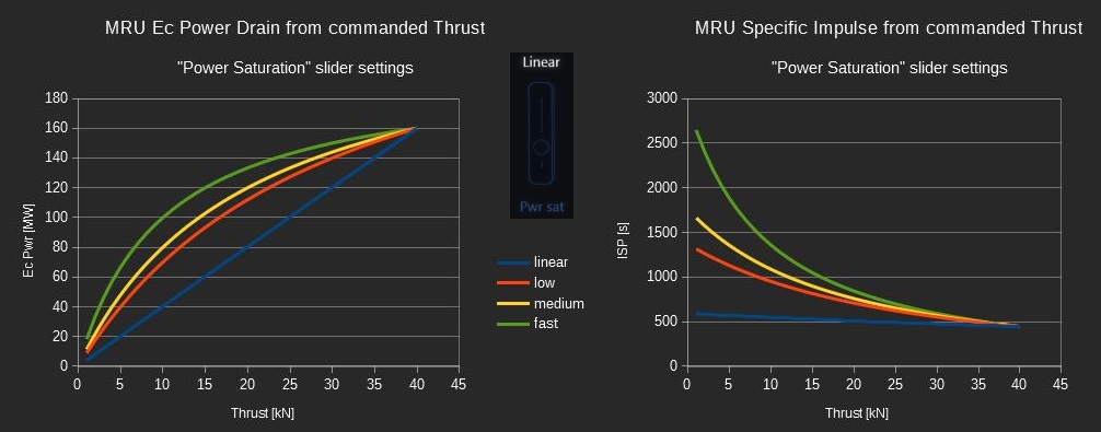
- The MRUs feature a backup array of cold-hydrogen thrusters to use when the available electrical power is strictly limited. The typical ISP is 255 s at low thrust and depends on the available pressure and temperature. The mode is activated through the power saturation slider (minimum setting).
Note: the term “maneuvering” may be misleading considering that MRUs are powerful engines in their own right and can draw large amounts of electrical power from the ship’s electrical system. Due to their relatively low ISP they may also consume large amounts of hydrogen and significantly affect the overall ΔV budget.
As a general rule: the lower the commanded MRU thrust and impulse, the better.
Flight Control Modes
The flight control matrix presents a summary of the available modes. From left to right:
- The mode and its intended use.
- Whether the main thrust is produced by the main engine or the MRUs.
- The corresponding Attitude and Thrust settings to be selected on the front helm panel.
- Whether the flight guidance system is active for the mode or not.
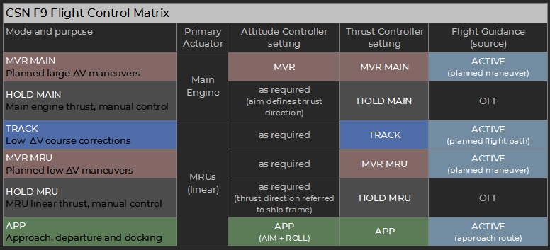
Note: the APP sub-modes are presented below.
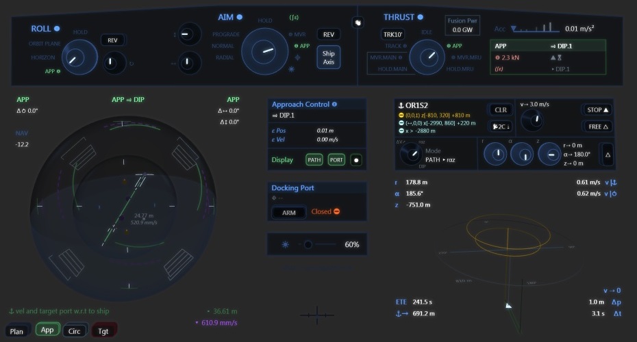
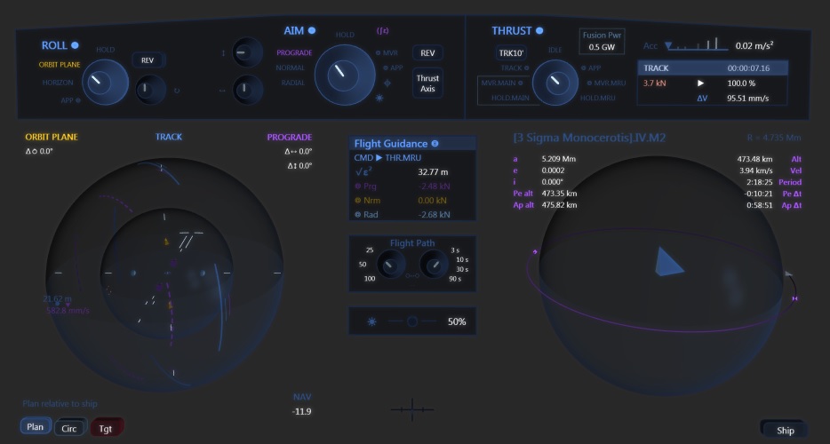
- Central console
Provides information about the approach controller state, toggles for navigation visualization aids and the docking port controls. - Relative Flight control panel
Features all the necessary controls to set the reference object (“anchor”), execute translations in its vicinity and dock to one of its docking ports. - 3D view
Displays a schematic view and information about the ship with respect to the reference object.
Reference Frame and Origin
Approach modes are flown relatively to a selected object, a space station most of the time. Its center of mass is the origin for all coordinates, and its orbital frame is used as reference:
- the Y axis is set along the prograde direction of the orbit (direction of the velocity vector),
- the Z axis is given by the oriented normal to the orbital plane,
- the X axis derives from Y and Z (and generally points away in a radial direction from the orbited celestial body).
However since all operations are centered on the reference object it is more convenient to express locations and command translations using the cylindrical coordinates (r, α, z) where:
- r is the distance from the Z axis,
- α measures the clockwise angle from the Y axis (defined as “0°”),
- z is the altitude w.r.t the orbital plane (positive above).
Restricted Flight Areas
- space elevator cable,
- orbital ring and link cable,
- planetary rings.
In approach mode the flight controller constantly monitors the ship’s location and velocity and will automatically take control and brake to a stop in case or imminent violation. It will also attempt to return to authorized space in case of effective trespassing.
Docking ports can only be accessed through a narrow corridor (of conical shape) extending from the port to the corresponding Docking Ingress Point (the DIP lies outside of the station’s restricted area).
Navigation Data
Facilities must provide the necessary flight information (restricted areas and docking ports) via a radio link. The process follows an automated protocol on the NavData channel set. The relative flight panel’s anchor section provides simple controls to easily set a comms unit slot as required and send a navdata request.
Approach Control Modes
The approach control matrix provides a summary of the related flight modes. From left to right:
- Mode designation,
- Command inputs,
- Description and additional notes.
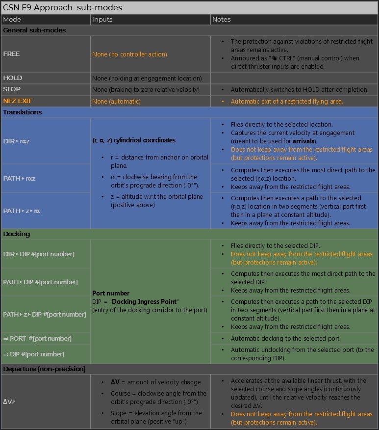
Note: the mode selector sets the displayed inputs (at its right) as required:
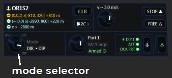
Translation velocity and MRU thrust
The desired velocity for all translations is set using the selector at the top right of the relative flight panel. The default is 3 m/s, please note that the ΔV cost of all moves heavily depends on this setting.
The flight controller will use all of the available linear thrust as needed (and which depends on the number of active MRUs and “LIN” slider allocation on the “Maneuvering Systems” panel).
Engagement process
The procedure requires two steps:
- Prepare then select the desired operation, which then becomes the “pending” APP mode,
- Press the “engage” control so that the pending mode becomes active.
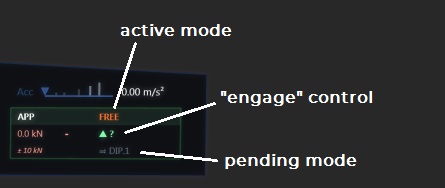
Most operations automatically prepare a subsequent pending mode: for instance the controller will plan to “HOLD” at the destination of a (r, α, z) translation. This step can also be automatic, for instance a “STOP” always engages a “HOLD”, whatever the pending mode.
NB: the main overall “APP” thrust mode should remain engaged during all relative flight operations.