Contents
Exhaust-Mass-Augmented Fusion Rocket
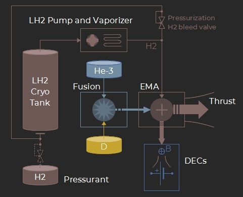
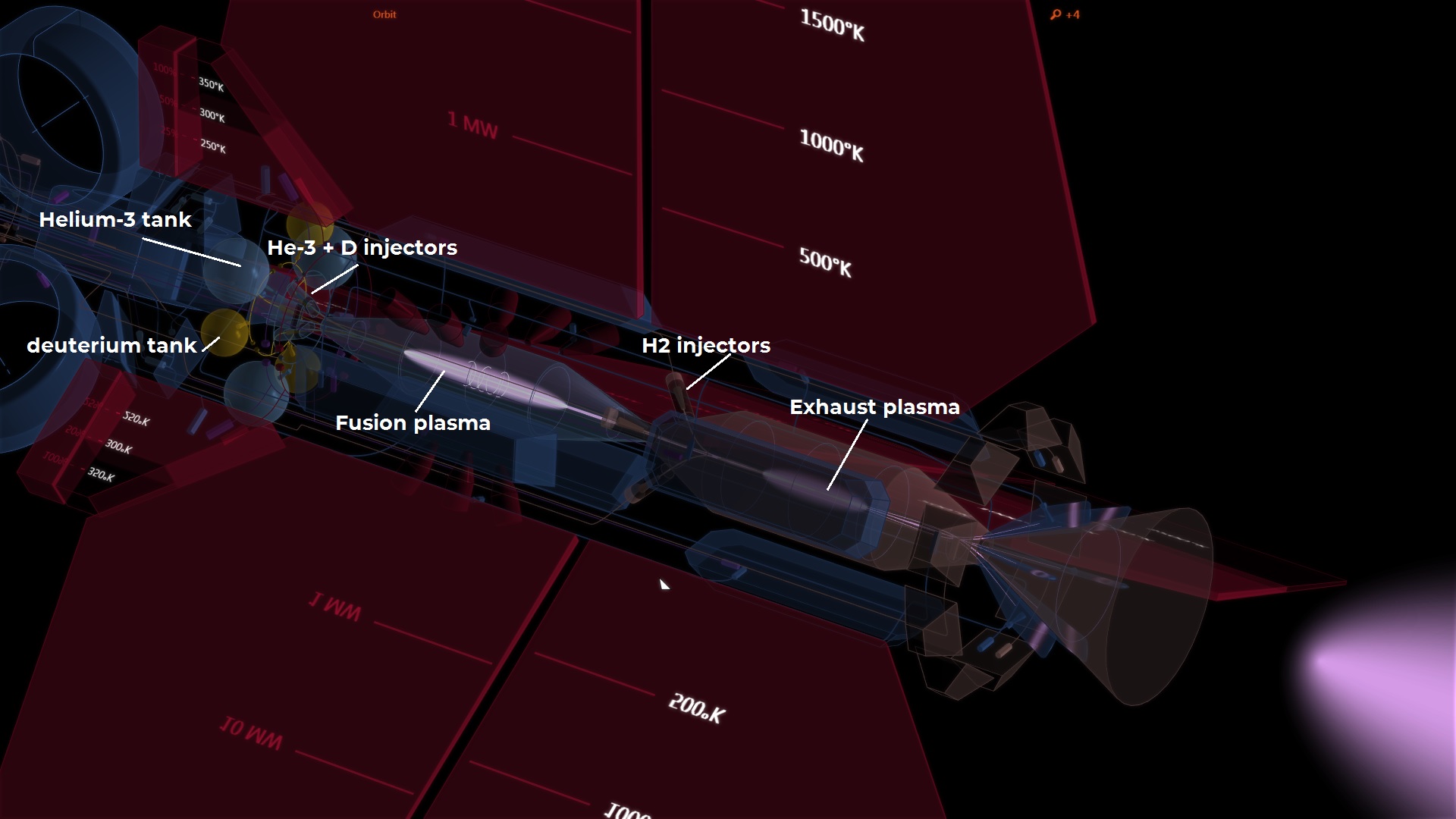
Like most modern spaceships the CSN F9 can be described as a single-stage exhaust-mass-augmented fusion rocket with the block diagram below:

- A fusion reactor (deuterium / helium-3) delivers a low mass flow rate stream of very high temperature plasma
typ: 280 keV, 2 g/s at 50 GW - The fusion plasma is mixed with hydrogen in the exhaust mass augmentation chamber (EMA) to produce a larger mass flow rate exhaust plasma at lower temperature
typ: 65 eV, 2.5 kg/s @ 460 kN thrust - The exhaust plasma is expanded into the magnetic nozzle to produce thrust yielding the desired acceleration and ΔV budget characteristics
type: 2.05 m/s², ISP 15 ks @ 460 kN thrust - Part of the exhaust plasma is bled to the Direct Energy Convertors (DECs) to generate electrical power
- The hydrogen propellant is stored in liquid form in pressurized cryogenic tanks.
Given a ΔV requirement a maneuver can be flown with many different thrust levels and reactor power settings. The thrust directly governs the acceleration and thus the burn time. The fusion power to thrust ratio must also be considered knowing that in average over the whole mission: ΔV budget · thrust = η · fusion power.
η is the conversion efficiency from the fusion thermal power to the of the expelled plasma’s kinetic power at the nozzle output.
It would appear that it is always best to use a large power to thrust ratio. However some equipment reliability considerations must be taken into account and in general:
- Running “lean“ at high-power, low thrust yields the highest ISP (exhaust velocity) and is therefore the most economical option (propellant flow = thrust / exhaust velocity). However this also means running hot and for a long time, which can significantly increase the wear rate on the power plant.
→ to be used when lower accelerations are suitable and with careful monitoring of the estimated wear rates. - Running “rich“, at high power and high thrust. This way is less taxing on the equipment (cooler), however the propellant flow is much higher and limits the total available ΔV.
→ to be used during tactical emergencies or difficult maneuvering situations (typically in deep gravity wells).
The table below shows the possible thrust regimes at maximum fusion power. The minimum thrust is limited by the reactor temperature and wear rate of the DECs. The maximum is set by the H2 injection system.

Also as you upgrade your ship you will be able to re-calibrate the flight controller’s internal reference performance data. This is very important because the flight planner also needs it to correctly model the ship’s mass all along the flight plans.

EMA “DEC” vs “THRUST” modes
Depending on the situation the fusion controller regulates different quantities in the EMA chamber:
- No main engine thrust: Electrical power generation or “DEC”
This correspond to stand-by situations whenever the ship is coasting (or using the maneuvering thrusters only). In this mode the fusion controllers optimizes the operation of the magnetohydrodynamic generators and regulates the exhaust plasma pressure and its temperature (adjusting the H2 injection stream and the flow of plasma fed to the DECs). - Main engine THRUST mode
In this configuration the fusion controller regulates the exhaust plasma pressure and the measured thrust (adjusting the H2 injection stream and the flow of plasma fed to the nozzle). The exhaust plasma temperature then derives from the power to thrust ratio and is not controlled. To sustain the electrical power generation while thrusting, the DECs are allocated a plasma flow yielding their nominal power rating for the current plasma temperature (it is possible to modulate this bleed flow target if needed).
Reactor power-up
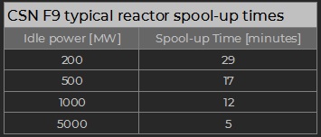
Spooling-up the reactor takes time and it must be ready before the main engine start, otherwise it is not be possible to generate the planned amount of thrust. Worse, trying to start the burn nonetheless is likely to trigger safety protections against a “bremsstrahlung flash“. This is what happens when the EMA is starting to accumulate a large quantity of plasma that correspondingly generates a large braking radiation, rapidly damaging the chamber’s lining.
Here are typical spool-up times:

Note: the target power is not specified as it makes little difference given the kinetics of the fusion reaction. Increasing the plasma mass as a fixed fraction of the fusion power leads to a solution with finite time to singularity (power → ∞). The behavior is not exponential as might be expected.
Powering-up ahead of time is to be avoided too: while the EMA remains in DEC mode regulating the temperature with a large flow of fusion plasma requires a correspondingly large flow of hydrogen that is wasted away. Also at high power levels the systems’ temperature might also become a problem. Under thrust the large flow of liquid hydrogen being evaporated and heated significantly participates to the cooling power. Without this effect overheating is likely and the wear rates increase.
As a captain you will always be in charge of the fusion power level and no automation will interfere with your choices. You will have to constantly adapt the reactor’s state to the ship’s situation (navigation, tactical considerations…) and anticipate ahead to balance operational response time with endurance and systems wear.
The following video illustrates the EMA DEC and THRUST modes, and how the ship’s advisory system provides help with the reactor’s power level management in practice.
Advanced demo of the reactor settings – accelerated spool-up, maximum power burn